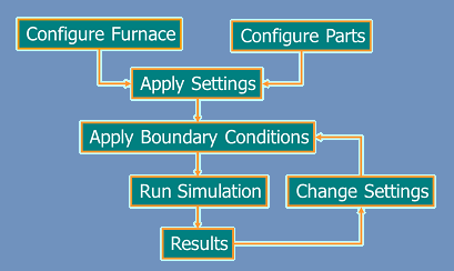
Analysis Method
Configure Furnace: The Furnace Configurator feature lets the user specify the furnace to be analyzed. The parameters required to configure a furnace are: furnace dimensions; thermocouple locations; insulation type, dimension, and thickness; muffle type (if applicable) and dimensions; belt width and weight; and process gas inlet location.
Create Part: Any type of part can be configured with FurnXpert. There are several shapes from which to choose. After selecting a shape, the user enters its dimensions and picks the material from a pull-down list. The newly created part is then saved in the database with a unique name, and can be recalled via the select part option.
Select Part: Any part that has been created can be selected to run the simulation. This is a powerful feature, because it not only enables the user to simulate the design part, but also allows what if analyses of other parts to determine whether they could be heat treated in the same furnace.
Place Parts: Once a part has been selected to process in the furnace, the part placement configuration must be specified. The user can run furnace simulations using different part orientations to determine the effects of part placement on furnace design and performance. Some of the inputs for part placement data include Container/Support type (Baskets, Trays, Peers, etc.), Part arrangement inside the container, and Container position inside the furnace.
Select Settings: After having configured a furnace and a part, selecting a part to run, placing the parts inside the furnace, the next task is to select the furnace settings. This feature enables the effects of different settings on parts and furnace to be assessed. The settings could be setpoint temperatures, process gas flows, and belt speed. Instead of temperature setpoints the user can also select temperature vs. distance.
Run Simulation: The analysis can be run after furnace parameters, part parameters, and operating conditions have been chosen. The analysis includes two steps. In the first, the software uses the finite element/lumped mass method to calculate the temperature of the part at every point along the length of the furnace.
The finite element method is a mathematical technique of breaking down a part into small elements and calculating the temperature for each individual element. So at every calculation step, the model simultaneously determines the temperature at several points on or inside the part. The model uses the furnace temperature profile as the boundary condition. The profile is determined from the temperature settings for each zone (for continuous furnace) or from the temperature setting during each heating or cooling stages (for batch furnaces).
In the second step, the software performs the heat loss calculations required to determine heat gained by the parts, belt, trays, and process gases, and heat lost through the insulation. These data are then consolidated to calculate the power requirement for each zone of the furnace.
Results: The results from the analysis include Furnace and Part Profiles, Setpoints and Production Rates, Furnace Heat Audit calculations with Sankey Diagram, Power requirements and energy consumption.
Reports: The results from FurnXpert are compiled in a report format available in PDF or Excel Format.